








Home Network Wiring Blueprint: Complete Guide to AV Network Setup
A single missed network connection can force AV installers to reroute cabling, revise equipment connections or revisit completed installation work. These problems often arise when residential network infrastructure is planned separately from the broader AV system design.
According to a Eurostat report, 67% of EU internet users used connected home entertainment devices in 2024, highlighting the growing demand for reliable connectivity across residential AV environments. As connected equipment increases, overlooked network drops, poorly coordinated cable pathways and limited port capacity can lead to installation rework and difficult future upgrades.
In this blog, we discover how a home network wiring diagram allows AV designers to map equipment locations, network drops, cable pathways and infrastructure requirements before deployment. It covers residential AV system design, networked entertainment, control systems and smart home expansion.
“Early AV infrastructure planning gives every device, cable and rack component a defined location, reducing last-minute changes during installation.” - Custom Controls
The all-in-one solution for your AV needs
Transform your audio-visual experience with XTEN-AV.
No Credit Card required
Key Takeaways
- A home network wiring diagram must map displays, AV receivers, media servers, control processors, wireless access points, IP cameras and other connected AV endpoints.
- Cat5e, Cat6 or Cat6A cabling should match bandwidth, distance, PoE and future expansion requirements for AV over IP and high-bandwidth video distribution.
- A dedicated network cabinet should accommodate the router, managed switch, patch panel, and AV equipment with adequate ventilation, thermal management, cable organization and expansion capacity.
- Structured cable pathways, correctly positioned network drops, clear labeling and separation from electrical wiring support reliable connectivity and simpler future service work.
- AV designers can prefer X-DRAW, a cloud-based AV CAD drawing software, for creating coordinated network diagrams, floor plans, rack elevations, cable schedules, and BOMs in one design environment.
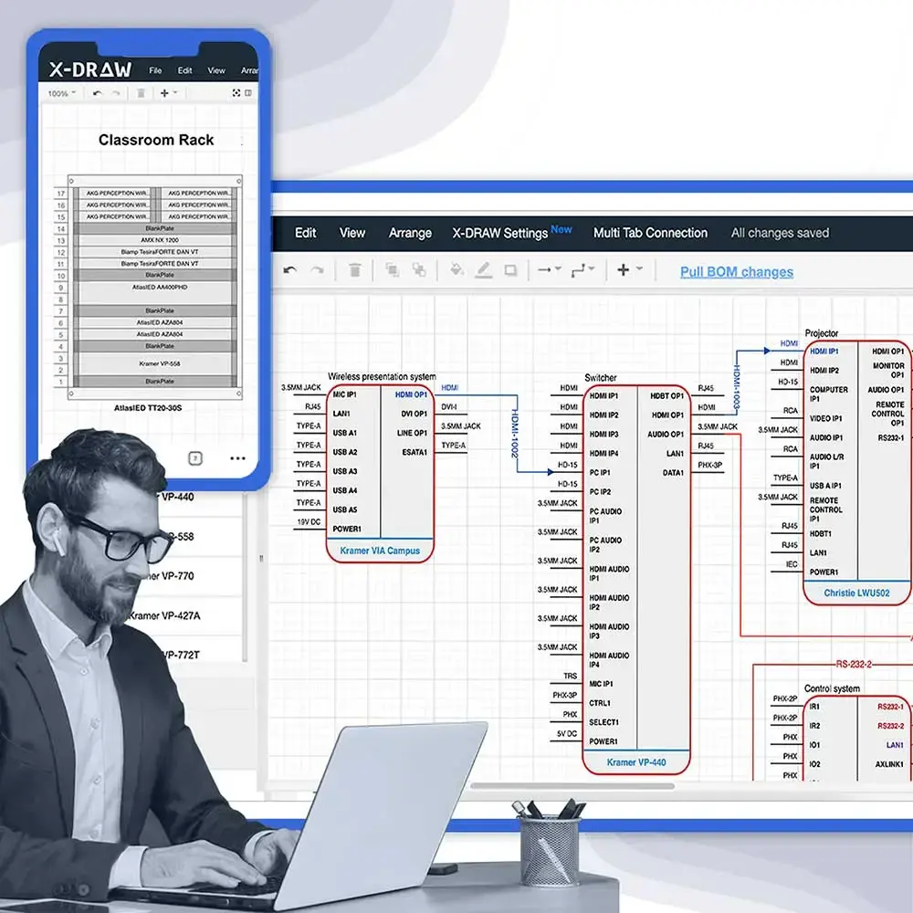
AV Design Mastery + Winning Proposals = 10x Productivity!
- Automatic Cable Labeling & Styling
- 100+ Free Proposal Templates
- Upload & Create Floor Plans
- 1.5M Products from 5200 Brands
- AI-powered ‘Search Sense'
- Legally Binding Digital Signatures
No Credit Card Required
How To Plan Your Home Network Wiring?
Proper planning is a critical step for ensuring reliable home network. Determining the factors such as device types, design layouts, cable selection, planning for WIFI access points and future proofing is must before starting the AV installation procedure. After that home network setup diagram creation process is involved for visualizing equipment placement which plays a major role in minimizing installation errors, simplifying cable management and maintain optimal network performance for connected AV devices.
1. Create a Home Network Floor Plan
Begin with architectural floor plan and start marking necessary location which is required for wired connectivity. This includes displays, AV receivers, computers, NAS devices, Wi-Fi access points, media servers, IP cameras and other networking equipment. By using the approach, it helps to ensure accurate home ethernet wiring diagram, making cable routing and equipment placement easier before starting the deployment procedures.
If creating a home network setup diagram from scratch feels time-consuming, use these AV design templates to plan faster and more accurately.
2. Choose the Right Ethernet Cable (Cat6 or Cat6A)
Selecting ethernet cables rely on requirements such as system’s bandwidth and future scalability requirements. Cat6 is mostly suitable for Gigabit Ethernet whereas Cat 6A is recommended for 10 Gigabit ethernet, PoE devices, AV over IP endpoints and high-bandwidth video distribution.
3. Design the Network Cabinet and Equipment Layout
Installing the modem, router, managed switches, patch panel and AV equipment requires a proper networking cabinet or home network wiring panel. Organizing network equipment in a dedicated enclosure improves airflow, enables proper thermal management, streamline cable management, also offers easy access for maintenance and troubleshooting procedures.
4. Map Structured Ethernet Cable Routes
Plan Ethernet cable pathways before starting the AV installing procedures. Cable routing using ceiling spaces, conduits, building pathways and cable trays is essential. Also, there is need to keep low-voltage cabling separate from electrical wiring to minimize the electromagnetic interference (EMI) and maintain signal integrity. Cable labeling is important so that testing is proper done and future system upgrades are possible whenever required.
5. Determine Ethernet Port and Wall Jack Locations
Always allocate ethernet ports based on current and future AV requirements. Assign dedicated network drops for display, wireless access points, control systems and equipment racks. Reserve additional ports to support future AV devices, network expansion and smart home technologies without additional cable runs.
Cat5e vs. Cat6 vs. Cat6A: Which Ethernet Cable Is Best for Home AV Wiring?
A reliable AV network involves choosing the appropriate Ethernet cable. These cables are classified into Categories (Cat), which is an industry level standard for defining the cable’s supported bandwidth, transmission speed and operating range. Selecting the right category enables stable connectivity for AV devices, also provide proper capacity for future upgrades. If your requirements are regarding home network design and installation projects, Cat6 is suitable for whom who wants the best balance of performance and value. Meanwhile Cat 6A is preferred for higher bandwidth AV deployments.
Common Ethernet Cable Categories Explained
Following is ethernet cable categories mentioned below which are commonly used in residential AV systems and structured network installation:
Cable Category | Definition | Maximum Speed | Ideal AV Applications |
Cat5e | Entry-level Gigabit Ethernet cable. | 1 Gbps | Basic residential internet wiring, smart home devices, HD streaming. |
Cat6 | Higher-bandwidth cable for modern Gigabit and short-distance 10 Gigabit Ethernet. | Up to 10 Gbps* | Smart TVs, AV receivers, Wi-Fi 6 access points, IP cameras, control systems. |
Cat6A | Enhanced Category 6 cable supporting 10 Gigabit Ethernet over longer distances. | 10 Gbps | AV over IP, 4K/8K video distribution, networked audio, PoE-powered devices. |
Note: Cat6 supports 10 Gbps up to 55 m (180 ft), whereas Cat6A supports 10 Gbps up to 100 m (328 ft).
6 Key Ethernet Cable Selection Factors
1.Conductor Material (Solid Copper vs. CCA)
Solid copper offers better conductivity, improved Power over Ethernet (PoE) performance and longer service life as compared to Copper-Clad Aluminum (CCA).
2.Shielding (UTP vs. STP)
Unshielded Twisted Pair (UTP) is mostly preferable of residential AV installations. Shielded Twisted Pair (STP) minimizes electromagnetic interference (EMI) in electrically noisy environments.
3.Cable Construction (Solid-Core vs. Stranded)
Solid-core cable is ideal for permanent structured cabling scenarios, meanwhile stranded cable is suitable for flexible patch connections.
4. Power over Ethernet (PoE) Compatibility
Check proper compatibility with PoE-powered devices such as wireless access points, IP cameras, touch panels and AV control processors.
5. Cable Jacket Rating (CM, CMR, CMP)
Jacket ratings are used for defining installation suitability based on building codes, including general-purpose, riser and plenum environments.
6. Future Bandwidth Requirements
Plan for AV over IP, 4K/8K video distribution, networked audio and future expansion. Fiber optic cabling is recommended for long-distance backbone connections.
If you are unsure which Ethernet cable suits your AV setup, read our AV cable wiring diagram guide to plan reliable home network connections.
UTP vs. STP: Which Cable Fits Your AV Installation?
Here are the differences between UTP and STP given below:
Feature | UTP (Unshielded Twisted Pair) | STP (Shielded Twisted Pair) |
Recommended Applications | Smart TVs, AV receivers, wireless access points, control systems, IP cameras and most residential AV installations. | AV over IP systems, equipment racks, digital signage and cable routes near electrical panels, HVAC equipment or other high-EMI environments. |
Installation Requirements | Flexible cable with standard RJ45 termination, making routing and installation easier. | Requires shielded connectors, proper grounding, and correct termination to maintain shielding effectiveness. |
EMI Protection | Suitable where electromagnetic interference (EMI) is minimal. | Reduces signal interference in electrically noisy environments. |
Cost | Lower material and installation cost. | Higher material and installation cost due to additional shielding and grounding requirements. |
Note: Defining cable specifications during the design phase improves network reliability, supports future AV expansion and keeps the home network cabling diagram aligned with installation and maintenance requirements.
What Are the Steps for Home Ethernet Wiring?
A residential network installation creates a clear path from AV system design and cable routing to final network commissioning. The following five steps cover the essential process:
- Mark Connection Points
Map displays, AV receivers, media servers, wireless access points, control processors, IP cameras, and other networked equipment on the floor plan. - Prepare Cable Pathways
Establish suitable routes through conduits, ducts, cable trays, or other building pathways. Keep low-voltage cabling separate from electrical wiring to reduce electromagnetic interference (EMI). - Run and Label Cables
Route Cat5e, Cat6, or Cat6A cable to each endpoint. Label both ends and leave adequate service slack for testing, troubleshooting, and future AV expansion. - Terminate Network Connections
Connect cables to keystone jacks, wall plates, or patch panels using a consistent T568A or T568B wiring standard for reliable device connectivity. - Test Before Commissioning
Use a cable tester to verify continuity and wire mapping. Compare the results with the home ethernet wiring diagram before connecting switches, access points, displays, and other AV equipment.
What Is the Installation Process for Home Ethernet Wiring for Effective AV Network?
A poorly routed cable or faulty termination can cause connectivity issues during AV commissioning. For home network wiring installers, the following steps cover cable routing, connection termination and testing for a reliable AV network:
- Installing Wall Plates: Based on your floor plan, select locations for your wall plates. Carefully mark the position of the low-voltage mounting brackets on the wall, then drill with an appropriate bit size. Screw the mounting brackets to the wall, making sure that they are level. Finally, attach the wall plates to the mounting brackets, aligning them carefully.
- Running Ethernet Cables: Start at your planned router or switch site. If you are running the cables through walls, you can use fish tape or even pull wire to help fish the cable through the wall cavities. Be sure to leave enough slack at either end of the cable for ease of termination. Follow this process with every wall plate location according to your routed cable plan.
- Connecting Cables to Jacks: Carefully strip a little outer jacket on both ends of the Ethernet cable, showing the twisted pairs inside. Organize the wires into the color code in either the T568A or T568B wiring standard. Insert the wires into the Keystone jack while assigning each wire its correct color order within its corresponding slot. Use a punch-down tool to secure wires strongly. On the other end of this cable, do the same to the patch panel if you have one or directly to the router/switch.
- Testing Your Home Ethernet Wiring: Run each cable through a cable tester, which will indicate whether the cable is sound and whether it is wired properly. Next, plug devices in at wall jacks and check for network connectivity. If you discover issues here, closely inspect your wiring and connections to attempt to determine mistakes.
Troubleshooting Common Issues For Effective Home AV Network Wiring
Even with the best of planning and installation, you may run into some issues while the home ethernet wiring installation is in progress or even afterward. The following are some common problems and troubleshooting for them:
No Connectivity:
- Check the Physical Connections: Make sure that all Ethernet cables are securely plugged into the wall jacks, the router/switch, and the devices. Use your AV ethernet cable diagram to double-check that the ethernet wiring colors align correctly in the connectors.
- Verify Power: Be sure that your router, switch (if in use), and modem are turned on and have lights that indicate activity.
- Check the Router Settings: Log into your router’s settings to check that it is set up properly. Ensure that it has selected the correct type of internet connection, for example, DHCP or PPPoE and that the network name or SSID and password have been set.
Slow Speeds:
- Test Cable Quality: With the help of a cable tester, test for faulty Ethernet cables. Replace any cable that fails your test.
- Overloaded Network: If many devices run high-bandwidth applications at the same time, it can slow down the network. You may be able to limit the number of devices on the network, or you could upgrade your internet plan to faster speeds.
- Router Placement: Be sure to keep the router in a central position and not put any walls or large furniture around it, which will make the signal weak.
Intermittent Connectivity:
- Loose Connections: Check all Ethernet cables for loose connections. Unplug and replug to have a tight connection.
- Cable Damage: Visible damage, like cuts or kinks, should be checked on the Ethernet cables. These kinds of cables can cause intermittent connectivity. Replace damaged cables.
Home Audio Visual Network Wiring Made Easy with X-DRAW
Planning a residential AV network becomes challenging when CAD drawings, network pathways, rack layouts, schematics and AV BOMs are managed separately. Platforms like X-DRAW, a cloud based AV CAD schematic drawing software, help AV designers coordinate these deliverables in one design environment.
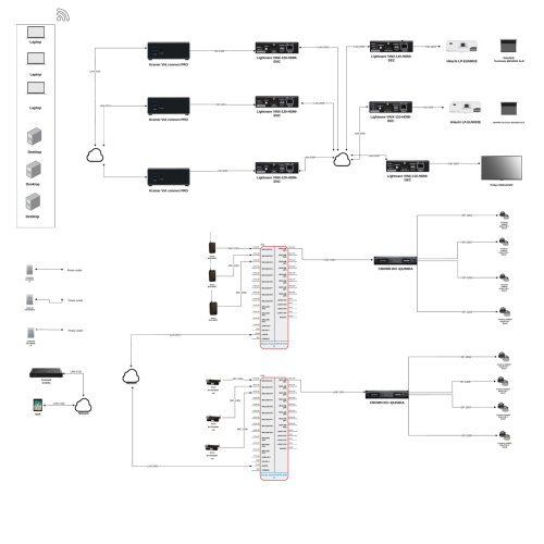
The following capabilities support more efficient AV network design and documentation:
- AV CAD Templates: Create floor plans, system schematics, network diagrams and rack elevations faster.
- Network Connection Visualization: Build an ethernet connection wiring diagram to show relationships between switches, endpoints and networked AV equipment.
- Connected Project Documentation: Keep AV drawings, cable details, equipment schedules, and AV BOMs aligned throughout the design process.
- Scalable System Planning: Account for additional network endpoints and AV equipment as the residential system expands.
For designers and integrators, X-DRAW brings CAD plans, system schematics, network diagrams, rack elevations and BOM generation into one patented AV system design platform.

AV Design Mastery + Winning Proposals = 10x Productivity!
- Automatic Cable Labeling & Styling
- 100+ Free Proposal Templates
- Upload & Create Floor Plans
- 1.5M Products from 5200 Brands
- AI-powered ‘Search Sense'
- Legally Binding Digital Signatures
No Credit Card Required
Conclusion
A reliable residential AV network depends on more than selecting the right Ethernet cable. Coordinating device locations, network drops, cable pathways, equipment placement, and future expansion before deployment creates a more organized and serviceable system. Effective home network cable management further simplifies maintenance as the AV environment evolves. For AV professionals seeking a unified design environment, X-DRAW brings network diagrams, floor plans, rack elevations, cable schedules and AV BOMs together on a cloud-based AV design and diagramming platform.
Still facing complex AV equipment connections? Explore AV wiring diagram software for faster, more accurate system design.
Ready to Plan Home AV Network Wiring Faster?
FAQs
A home network wiring diagram represents how routers, switches, patch panels, Ethernet outlets, Wi-Fi access points and AV devices connect across a home.
A home network wiring diagram allows AV integrators plan cable routes, equipment locations, network ports and device connections before installation stage.
A star topology with structured Cat6 or Cat6A cabling is the preferred layout for most residential network and AV installations.
A home network setup diagram must include the modem, router, network switch, patch panel, Ethernet outlets, wireless access points and connected AV equipment.
Cat6 is suitable for most residential networks, while Cat6A is better for 10-Gigabit Ethernet, AV-over-IP and future network expansion.
A router connects the home network to the internet, a switch connects wired devices, and a patch panel organizes Ethernet cable terminations.
X-DRAW is an AV CAD drawing platform that helps AV designers create network diagrams, floor plans, cable schedules, rack elevations and AV BOMs.