







Audio Visual (AV) Rack Units Guide: How to Calculate Rack Space

Sahil Dhingra
Published 26 May 2026
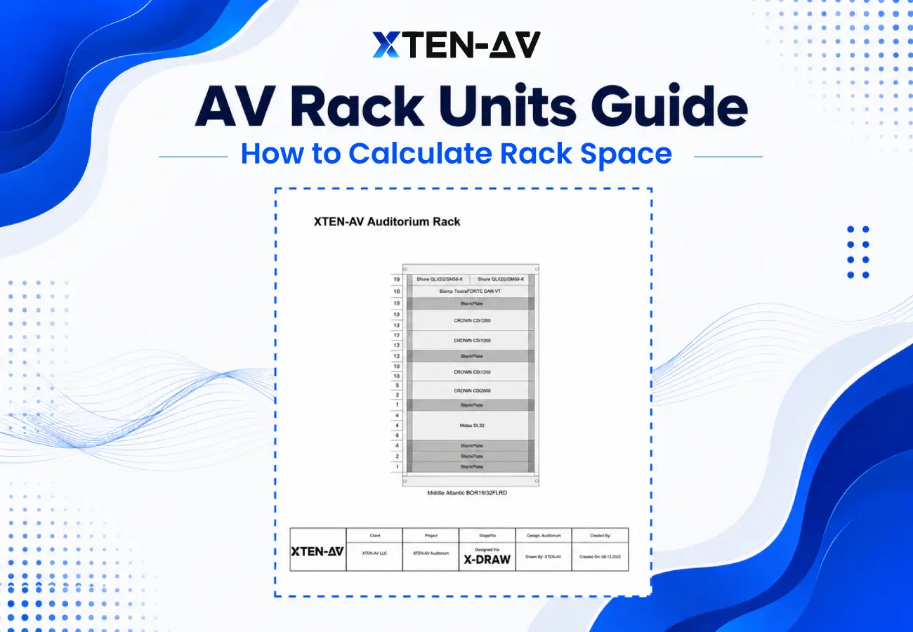


Most AV rack problems do not start during installation. They start during rack unit calculation.
The incorrect rack unit leads to wrong rack height measurements. The situation creates excessive rack usage which results in airflow problems and expensive onsite corrections.
AV rack units define the vertical space required for rack-mounted equipment before creating a rack layout or rack elevation. The system prevents design delays and field errors while it enables construction of a functional rack system that operates in actual environments.
This guide is for AV designers, integrators, and commissioning engineers translating a BOM into a buildable rack. Here is what it covers:
- What a rack unit is and how to read U sizes
- How to calculate rack space for any AV system
- A sample calculation for a conference room rack
- How much buffer space to leave
- How rack units connect to rack elevation diagrams
- Common planning mistakes and how to avoid them
Once the rack space is calculated, AV teams use XTEN-AV’s rack diagram tool to convert the equipment list into an accurate rack elevation before installation begins.
Key Takeaways
A rack unit (U) equals 1.75 inches of vertical space. Every device in your rack has a U size, get that wrong and the entire rack elevation is wrong.
Use this formula: Equipment U + Ventilation U + Cable/Power U + Future Expansion U = Required Rack Space.
Always reserve a 15-25% buffer above your total U count for airflow, cable management, and future additions.
Vent panels and blank panels are not optional. They control airflow and prevent heat buildup from amplifiers and DSPs.
Check rack depth, not just rack height. A device that’s 20 inches deep won’t fit a 15-inch-deep rack.
The U count is just the starting point, it must be converted into a rack elevation diagram before installation begins.
X-DRAW turns your equipment list into a complete, installer-ready rack elevation connected to your BOM and signal flow diagrams, no manual drawing required.
The all-in-one solution for your Audio Visual (AV) Project Design & Documentation needs
Transform your audio-visual experience with XTEN-AV.
No Credit Card required
What Is a Rack Unit in Audio Visual (AV) Rack Design?
A rack unit (U or RU) is a standardized measurement equal to 1.75 inches of vertical space inside a 19-inch rack enclosure which serves as the standard measurement used in AV system design. The 19-inch figure refers to the width of the mounting rail, not the overall cabinet width.
Rack-mounted AV devices are manufactured to occupy some U of vertical space. If a device is 1U, it is 1.75 inches tall. 2U would make 3.5 inches. A 4U device is 7 inches. The U count adds up directly to the total rack height you need.
Rack Unit | Height | Common AV Use |
1U | 1.75 inches | DSPs, patch panels, network switches, slim receivers |
2U | 3.5 inches | Amplifiers, matrix switchers, mid-size control processors |
3U | 5.25 inches | Large UPS units, multi-zone amplifiers |
4U | 7 inches | Large power conditioners, specialist AV equipment |
In practice, rack units are not just measurements. A rack elevation diagram shows how everything is placed inside the rack, while one must also be aware of how the system behaves when in place.
Rack unit planning becomes more accurate when it is connected to Audio visual (AV) system integration software that also manages drawings, BOMs, and signal flow diagrams.
How Do You Calculate Rack Space for Audio Visual (AV) Equipment?
Calculating AV rack units is not just about adding equipment height. The process needs to assess airflow requirements together with cable distribution paths, power equipment needs and future system growth needs before constructing the rack system.
The Formula to calculate AV Rack Space: Required Rack Space = Equipment U + Ventilation U + Cable/Power U + Future Expansion U |
Step 1: Gather all equipment information from the BOM
The equipment list should be obtained from the Bill of Materials which requires you to include all equipment that needs to be mounted in a rack.
Step 2: U size of each device needs to be documented
The manufacturer specification sheet contains information about the U height of every rack-mounting device.
Step 3: Install both shelves and cable management units
Horizontal cable managers typically take 1U each. Factor them in early.
Step 4: Add vent panels and blank panels.
Vent panels keep airflow moving. Blank panels fill unused space and block heat circulation.
Step 5: Add power devices.
PDUs and UPS units take up rack space too. A standard rack-mount PDU is typically 1U. A UPS has a size range that extends from 2U to 3U.
Step 6: Add 15-25% expansion space.
AV systems grow. Clients add screens, mics, and zones. Build in the room now.
Step 7: Convert the total into a rack elevation.
A rack elevation diagram maps each device to a U position in the rack. This is the output you handover to your installer.
At this stage, you have a total U requirement, but not yet a buildable rack. That total must be translated into a rack elevation diagram to guide installation.
Sample Rack Unit Calculation for a Conference Room AV Rack
Here is a practical demonstration. The configuration of the system includes a mid-size conference room which contains a matrix switcher, an amplifier, a DSP device and a control processor.
Equipment | U Size | Notes |
DSP | 1U | Handles audio routing and EQ |
Network Switch | 1U | Connects AV and control devices |
Wireless Receiver | 1U | Wireless mic system |
Control Processor | 1U | Room control and automation |
Matrix Switcher | 2U | Handles multiple video inputs/outputs |
Amplifier | 2U | Multi-channel audio amplification |
PDU | 1U | Rack power distribution |
Vent Panels | 2U | Airflow management above heat sources |
Future Expansion | 3U | Reserved for additions |
TOTAL | 14U | Plan for a 16-17U rack to allow buffer |
Calculating total rack units gives you a baseline, not the final rack size.
AV integrators choose the final rack based on installation constraints, equipment behavior, and serviceability.
If your total is under 10U → A 12U rack is typically sufficient for compact systems.
If your total is 12–16U → Choose an 18U rack to allow airflow and expansion.
If your system includes UPS, high-power amplifiers, or dense cabling → Move to the next rack size category.
If the rack is installed in a tight AV closet → Leave additional spacing for service access.
Experienced AV professionals rarely size racks exactly to the calculated U count. A slightly larger rack prevents airflow issues, cable congestion, and redesign later.
How Much Extra Rack Space Should AV Integrators Reserve?
The industry standard is 15-25% buffer space above your total U count. This is not wasted space. It is built-in insurance.
Why Buffer Space Matters:
- Thermal load management: Amplifiers and DSPs generate concentrated heat inside a closed rack enclosure which rises vertically. When high-draw devices are stacked without spacing, the thermal load compounds and the device above runs hotter than it should. Over time, this shortens component life and triggers shutdowns. Place vent panels directly above high-draw devices to break the heat stack.
- Airflow path integrity. Blank panels are not cosmetic. They force airflow from bottom to top through the equipment. An open gap creates a recirculation point where hot exhaust air pulls back in from the front. So, fill every unused U with a blank or vent panel.
- Cable bend radius and routing space. Dense cable bundles restrict rear airflow and force cable bends below the minimum bend radius, especially HDMI, fiber, and Cat cable. Use horizontal cable managers between device groups. They protect signal integrity and make individual cable tracing possible without disturbing adjacent runs.
- Service access clearance. A packed rack means a technician replacing one DSP will disturb three other cables. Leaving at least 1U of clearance between major equipment groups reduces the risk of accidental disconnection during maintenance.
- Future expansion. AV systems expand usually within 12 months of handover. A rack with zero buffer is a redesign project waiting to happen.
Ignoring these factors does not just reduce efficiency, it leads to overheating, signal issues, and on-site redesign.
Airflow and Buffer Rules at a Glance
|
Which AV Equipment Uses Rack Units?
Most rack-mounted AV equipment ships in standard U sizes. Here is a reference guide for common devices.
Equipment | Typical U Size | Notes |
Amplifier | 2U | Varies by channel count and output power |
DSP | 1U | Some multi-zone DSPs are 2U |
Network Switch | 1U | Standard managed switches are 1U |
UPS | 2U–3U | Size depends on power load and battery capacity |
Patch Panel | 1U | 24-port or 48-port, both typically 1U |
Control Processor | 1U | Enterprise models may be 2U |
AV Receiver | 2U–3U | Rack-mount receivers vary; check spec sheets |
PDU | 1U | Basic rack-mount PDUs are 1U |
Matrix Switcher | 1U–4U | Depends on port count; larger units are 4U |
Vent / Blank Panel | 1U | Both are 1U; vent panels allow passive airflow |
Cable Manager | 1U | Horizontal cable managers sit between devices |
Always verify U sizes in the manufacturer’s technical datasheet. Do not rely on catalog images or generic listings.
How Do Rack Units Affect Rack Elevation Diagrams?
A rack elevation diagram is a visual map of the entire rack. Every U position is drawn to scale. Each device is shown in its exact location, from top to bottom of the rack. It is the single most important document the design team hands to the installer.
Rack units define everything in that diagram. The U size of each device determines how many rows it occupies. The sequence of devices determines the load balance, airflow path, and cable routing.
Here is how U planning affects the rack elevation directly:
- Heavy equipment (UPS, amplifiers) goes at the bottom to keep the rack stable.
- Heat-generating equipment goes in the middle with vent panels above.
- Network gear and control processors go near the top for easy access.
- Patch panels go at the top or bottom, close to cable entry points.
- Blank panels fill any empty U space to seal airflow paths.
If U sizes are wrong at the planning stage, the rack elevation is wrong. And an incorrect rack elevation means rework on site, which costs time and money.
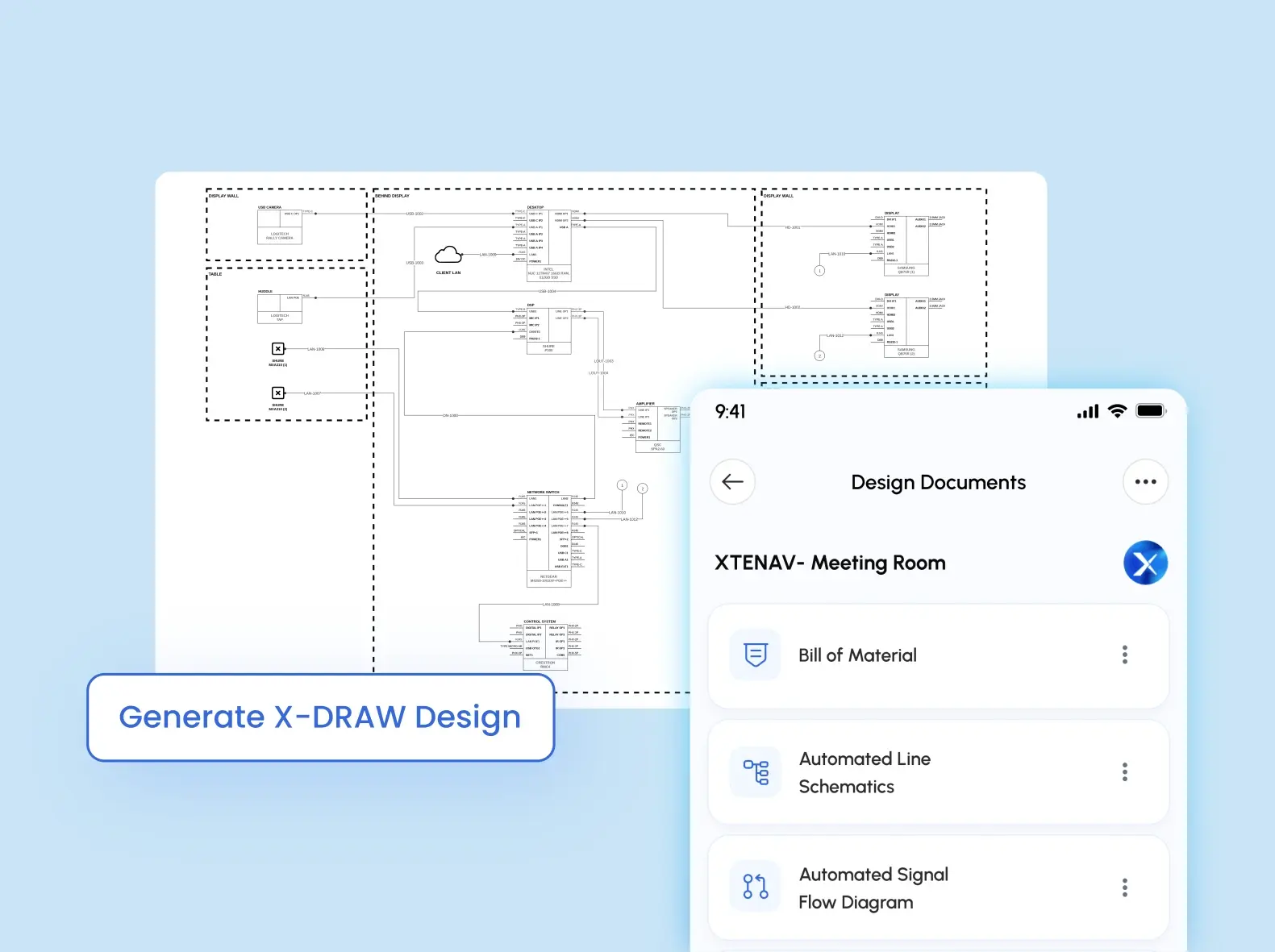
That is where XTEN-AV changes the workflow. X-DRAW does not just build the rack elevation, it connects it to the full AV drawing set. Signal flow diagrams, line schematics, and the rack layout all live in the same project file.
Change a device in the rack and the connected drawings update too. The installer gets one complete, accurate package, not three separate documents that may or may not match each other when using XTEN-AV platform.
Common Rack Unit Planning Mistakes
Avoid these common AV rack cable management mistakes. that delays projects.
1. Ignoring Airflow
Packing equipment with no vent panels causes heat buildup. Amplifiers and DSPs fail first. Always plan vent panels around high-heat devices.
2. No Cable Space
Skipping cable managers leaves cables dangling across equipment. It blocks airflow. It makes changes painful. Plan 1U cable managers between device groups.
3. No Future Expansion
A full rack with zero buffer is a problem waiting to happen. Reserve 15–25% extra before you close the design.
4. Not Checking Rack Depth
Rack height gets all the attention. Rack depth gets ignored. A device that is 20 inches deep will not fit a 15-inch-deep rack. Check AV rack depth and height before specifying any equipment.
5. Poor Equipment Placement
Placing heavy UPS units at the top makes the rack top-heavy. Placing power gear next to control processors creates interference. Equipment placement is not just aesthetic — it is functional.
6. No Final Documentation
Completing the install without updating the rack elevation is a handover failure. The as-built rack elevation must match what was installed. Future technicians will thank you.
How XTEN-AV Helps AV Teams Plan Rack Space Faster?
Once the U count is done, most AV teams hit the same wall: translating a spreadsheet equipment list into an accurate rack elevation diagram. Traditionally, this happens in AutoCAD, Visio, or generic drawing tools, none of which understand AV.
They do not know what a DSP is. They do not know how signal flow connects to rack position. They require manual drawing, BOM reconciliation, and documentation updates every time something changes.
XTEN-AV removes that gap with X-DRAW.
X-DRAW: From U Calculation to Rack Elevation in One Step
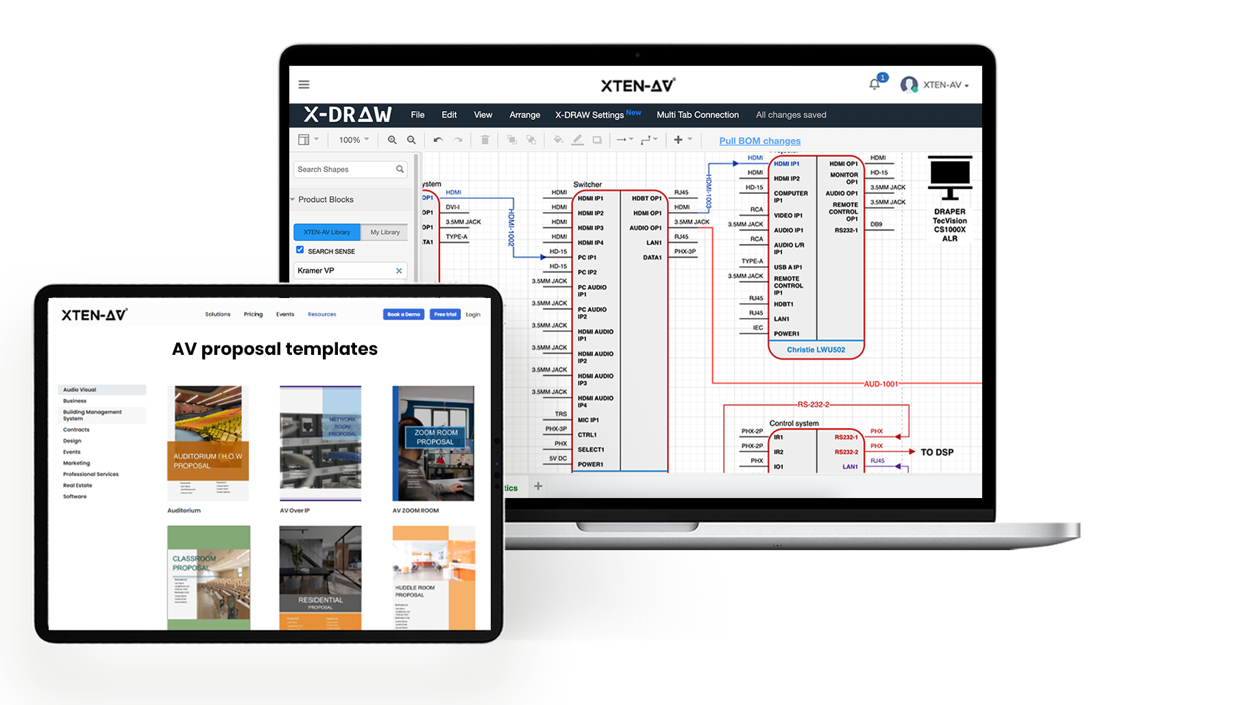
X-DRAW is purpose-built for AV system design, not adapted from an IT or architecture tool. It understands AV device types, signal paths, and rack structure natively. When you bring in your equipment list, X-DRAW places each device at the correct U position in the rack elevation automatically.
What X-DRAW produces from a single project file:
- Rack elevation diagrams drawn to scale which are U-accurate and installer-ready.
- Signal flow diagrams that map how every device connects.
- Line schematics for commissioning and troubleshooting reference.
- An auto-generated BOM that stays in sync with the rack design throughout the project.
The result is a rack elevation that reflects the real system, not a manual approximation built in a tool that has no concept of AV workflow.
Rack Space Planning Checklist
Use this checklist before freezing your rack design to avoid installation issues and rework.
RACK SPACE PLANNING CHECKLIST | |
☐ | Count the U size of every rack-mounted device from the BOM. |
☐ | Verify rack depth against the deepest device in the equipment list. |
☐ | Add ventilation space — vent panels above amplifiers and DSPs. |
☐ | Add horizontal cable managers between equipment groups. |
☐ | Include PDU and UPS in the total U count. |
☐ | Reserve 15–25% buffer for future expansion. |
☐ | Create or update the rack elevation diagram with correct U positions. |
☐ | Update the as-built documentation to match the installed rack. |
The all-in-one solution for your AV needs
Transform your audio-visual experience with XTEN-AV.
No Credit Card required
Audio Visual System Design Mastery + Winning Proposals = 10x Productivity!
- ✔ Automatic Cable Labeling & Styling
- ✔100+ Free Proposal Templates
- ✔ Upload & Create Floor Plans
- ✔1.5M Products from 5200 Brands
- ✔ AI-powered ‘Search Sense'
- ✔Legally Binding Digital Signatures
Conclusion
AV rack units are not a technicality. They are the foundation of every buildable rack design.
Get the U count right, and your rack elevation is accurate. Your installer knows exactly what goes where, cable management works, airflow holds and when the client adds equipment six months later, you have room for it.
Get it wrong, and you are reworking the design on site, with real time and real money on the line.
The process is straightforward. List your equipment. Note the U sizes. Add space for ventilation, power, and cables. Reserve 15–25% for growth. Then convert that plan into a rack elevation diagram before anyone touches the rack.
XTEN-AV makes that last step faster. Your equipment list becomes a visual rack layout connected to your BOM, your documentation, and your installer handoff without the back-and-forth.
Use XTEN-AV to create your AV rack layout and follow Audio Visual (AV) rack design best practices before equipment is ordered.
Ready to Plan Your Rack?
FAQ's
The measurement of one rack unit also referred to as 1U requires 1.75 inches of vertical space inside rack enclosures. The standard unit of measurement used for all audio visual equipment that is mounted on racks begins with this base unit.
List every rack-mounted device. Note the U size of each. Add vent panels, blank panels, cable managers, PDU, and UPS. Then add 15–25% for future expansion. That total is your minimum rack size.
Leave 15–25% beyond your total equipment U count. This covers airflow gaps, cable management, future additions, and service access.
It depends. A basic conference room with a DSP, switch, control processor, and small amplifier can fit in 12U. But any wireless receivers, UPS, or matrix switcher will push you to 16U or more. Always calculate first.
Rack height is measured in U, it is the vertical space inside the rack. Rack depth is measured in inches, it is how deep the rack enclosure is, front to back. Both matter. Check AV rack depth and height for standard dimensions.
Yes. Empty U space is not wasted. Blank panels block airflow leakage. Vent panels promote cooling. And empty space absorbs future additions without a redesign.
Every device in the rack elevation is placed according to its U size. If U sizes are incorrect, the elevation is wrong and installers mount equipment in the wrong positions. Accurate U data is the foundation of every accurate rack elevation.
Yes. XTEN-AV converts your equipment list into a visual rack layout and rack elevation diagram connected directly to your BOM and project documentation.
Explore more by topic

AV Design Mastery + Winning Proposals = 10x Productivity!
- Automatic Cable Labeling & Styling
- 100+ Free Proposal Templates
- Upload & Create Floor Plans
- 1.5M Products from 5200 Brands
- AI-powered ‘Search Sense'
- Legally Binding Digital Signatures
No Credit Card Required
Related Blogs

-

- Posted by Sahil Dhingra

Audio Visual A Complete Guide to Commercial AV Companies: What to Expect,...

-
- Posted by Sahil Dhingra
Audio Visual 6 Best Field Service Management Software for Audio Visual (AV)...
-
- Posted by Sahil Dhingra
Audio Visual What Is an AV Connection Check and Why Does It...
