


Commercial Ceiling Speaker Layout Guide for Audio Visual (AV) Projects

Sahil Dhingra
Published 02 June 2026
Commercial ceiling speaker layout is the process of selecting speaker type, spacing, coverage pattern, and system architecture to deliver even voice and music coverage in business environments.
You finish the ceiling speaker layout, mapped the room, ordered the equipment. Then the email comes in. The conference room moved, the break area got bigger and they want the patio covered now too.
This happens on almost every commercial AV project. And when it does, the layout math, the CAD drawing, the equipment list, and the proposal, all built in separate tools have to be rebuilt from scratch. Not because the design was wrong. Because the documentation couldn’t keep up with the change.
Commercial ceiling speaker layout is a design problem before it’s a placement problem. Get the spacing wrong and you get dead zones where paging drops out, or excessive overlap that creates phase problems and muddy speech. Get the documentation wrong and a single client revision costs you half a day.
This guide covers the core decisions: ceiling height, dispersion angle, system architecture, use case, and how each one changes the layout. It also covers where most installs go wrong, and how to build a workflow where a scope change updates the design without breaking the proposal.
Key Takeaways
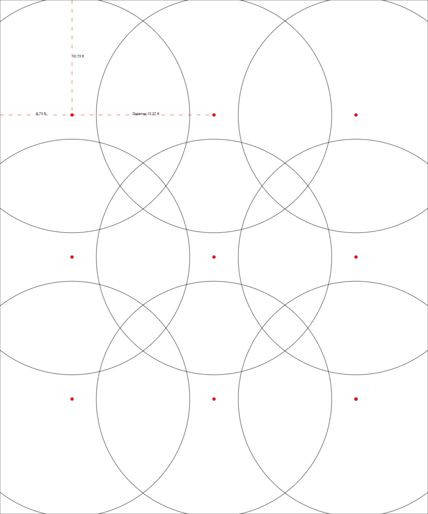
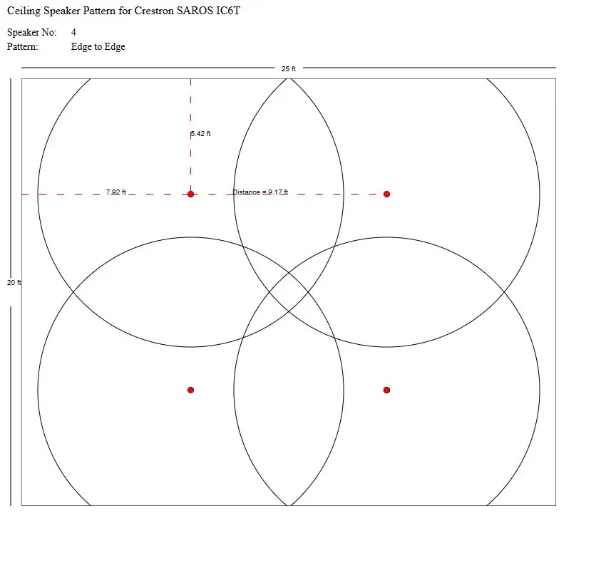
Spacing makes or breaks the layout. Too far apart and you get dead zones. Too close and you get phase problems. Target 3-6 dB of overlap between every adjacent coverage zone.
Ceiling height changes everything. It affects coverage radius, SPL at the listening plane, and how many speakers the room needs. The floor area alone gives you the wrong number every time.
Design for the use case, not just the room. Speech, music, and paging each need a different layout. Mixed-use spaces get designed to the most demanding requirement, usually paging.
Corners fail first. A grid optimized for the center of a room routinely under-covers the last 5-8 feet of each corner. Plan corner coverage explicitly. Don’t assume the nearest speaker handles it.
70V is the right call once the project scales. Cable runs over 50-100 feet, more than 8 speakers on a channel, or per-speaker volume control, any one of those points to 70V architecture.
The layout is only as good as the documentation behind it. One client change can break a floor plan, equipment list, and proposal all at once, if they’re built in separate tools. A connected workflow is what keeps the chain from breaking.
The all-in-one solution for your Audio Visual (AV) Project Design & Documentation needs
Transform your audio-visual experience with XTEN-AV.
No Credit Card required
What is a Commercial Ceiling Speaker Layout?
Commercial ceiling speaker layout means picking the right speaker type, spacing, and system design. The goal is simple. Every person in the room hears audio at the same level.
Residential spaces are built around one or two listening positions. Commercial spaces have no sweet spots: every seat, checkout lane, and table is a listening position. The layout has to work for all of them at once.
That is what makes it hard. Rooms are irregular. Ceilings vary. HVAC ducts block cable paths. Clients add zones mid-project. A good layout handles all of that. A bad one breaks the first time the scope changes.
The same principles apply across offices, retail floors, restaurants, hotel lobbies, classrooms, conference centers, and warehouses. The audio requirements of each space differ because its noise level and room shape and audio goal are distinct.
What Changes Ceiling Speaker Quantity and Spacing?
Four things drive the answer. Room shape. Ceiling height. Dispersion angle. And what the audio is for. Miss one and the layout is wrong before the first speaker goes in.
Room dimensions
Square footage gives you a baseline. Shape causes the problems.
The L-shaped office space of 4,000 sq. ft. presents greater covering difficulties than the 4,000 square foot box. The design requires special treatment of its alcoves and columns and partition walls. A basic area formula won’t catch them.
Long rooms lose SPL from one end to the other. End zones need their own coverage plan. Don’t just push the grid outward from the center.
Ceiling height
Most field callbacks start here. Ceiling height doesn’t just affect speaker count. It changes the coverage radius of every speaker in the system.
A 90-degree speaker at 10 ft covers an 8–10 ft radius at the floor. Raise it to 16 ft and the radius grows. But SPL drops. Each listener is further from the source
Coverage Radius Formula:
- r = coverage radius
- h = mounting height
- θ = dispersion angle
You need to check SPL at the listening plane to confirm your ambient noise target because the radius measurement cannot determine whether the speaker produces sufficient sound.
Higher ceilings mean fewer speakers per square foot, but the SPL budget tightens. That’s why ceiling height affects both quantity and spacing strategy.
Speaker dispersion angle
Most ceiling speakers have a dispersion spec between 90 and 120 degrees.
Narrow patterns concentrate sound. But they leave gaps. You need tighter spacing to close them.
Wide dispersion improves overlap consistency but can reduce intelligibility in reverberant environments.
Think of a tiled kitchen or a concrete warehouse. Wide dispersion makes speech worse in those spaces. A tight-pattern speaker placed with care beats a wide one placed without thought.
Audio objective
Speech-first rooms need tighter spacing. The benchmark is STI (Speech Transmission Index) above 0.6 and hitting that means maintaining a strong direct-to-reverberant ratio at every seat. That translates to more speakers, closer together, with deliberate overlap at zone edges.
Music-first spaces give more flexibility. A 4-5 dB SPL variation across a retail floor is tolerable in a way it wouldn’t be in a training room. The math works out differently.
Quick spacing reference by ceiling height:
Ceiling Height | Speaker Spacing | Recommended Use | Notes |
8–10 ft | 8–12 ft | Offices, classrooms | Tighten for STI > 0.6 |
10–14 ft | 10–14 ft | Retail, hospitality | Verify 3–6 dB overlap |
14–20 ft | Calculate from dispersion + SPL | Warehouses, large retail | High-output speakers required |
20 ft+ | Per design only | Industrial, atriums | Horn-loaded / pendant speakers |
Always target 3-6 dB of overlap at the edge of adjacent coverage zones. Less than that and the gap will be audible. More than that in a live room and phase problems start.
When Are Ceiling Speakers Better Than Wall Speakers in Commercial Spaces?
Wall speakers create hot spots near the source and drop off fast with distance. Ceiling speakers close that gap by bringing the source directly above the listener: less distance, SPL needed, and less energy feeding the reverberant field.
Choose ceiling speakers when:
The floor plan is open with no fixed listener orientation
Wall-level obstructions: shelving, partitions, columns would block coverage
Paging needs consistent reach across a wide area
Zoned background music follows room function, not room perimeter
Architectural integration matters and visible hardware isn’t acceptable
Wall speakers still work in:
Narrow corridors
Cinema lobbies
Boardrooms where everyone faces the front
For a detailed comparison, see our guide on in-wall vs in-ceiling speakers.
How Speech, Music, and Paging Each Change the Layout?
Most ceiling speaker guides treat this as a footnote. It shouldn’t be. The audio use case is the design brief. Room dimensions tell you how big the canvas is. The objective tells you how to design for it.
Factor | Speech-First | Music-First | Paging |
Primary metric | STI > 0.6 | SPL consistency | 100% coverage |
Spacing | Tighter | Wider OK | Tighter + corners |
SPL tolerance | ±2–3 dB | ±4–6 dB | Above noise floor |
Speaker density | Higher | Moderate | Highest |
Common spaces | Boardrooms, classrooms | Retail, hospitality | Warehouses, schools |
Speech-first rooms
Boardrooms, classrooms, conference rooms, and training spaces are speech-first environments. Intelligibility is the primary metric. These rooms need:
- Tighter speaker spacing to maintain high direct-to-reverberant ratio
- Speakers placed to minimize early reflections from walls and hard surfaces
- Higher speaker density than a music-only space of the same size
- Careful overlap planning so no seat is in a coverage gap
You will find speaker placement in a 30-by-40-foot classroom with a 10-foot ceiling through a 3×4 grid pattern which provides even coverage and maintains STI levels above 0.6. Background music can be played in the same room through a 2×3 grid setup.
Music-first spaces
Retail stores, hotel lobbies, restaurant dining rooms, fitness facilities. The goal shifts from intelligibility to SPL consistency and tonality. Listeners aren’t parsing speech, they’re experiencing an acoustic environment.
Zone boundaries follow room function: bar, dining floor, patio, entrance. Each gets its own volume control. Music-first layouts tolerate slightly wider dispersion and fewer speakers per zone without the intelligibility penalty that shows up in a classroom.
Paging systems
Commercial paging is a different problem. The requirement is 100% coverage, not ‘most of the room. Every square foot, including back corners, transition zones, stairwells, and loading docks.
Corners are where paging layouts fail. A standard grid optimized for the center of a room routinely under-covers the last 5-8 feet of each corner. That’s large enough to miss an emergency announcement. Plan corner coverage explicitly, don’t assume the nearest grid speaker handles it.
Paging systems almost always land on 70V architecture, which affects how tap levels are distributed across the circuit.
Mixed-use spaces
A restaurant running background music during service, making table announcements, and needing emergency evacuation through the same speakers is a mixed-use environment. The rule: design to the most demanding requirement.
In practice, that means paging intelligibility standards set the layout. DSP programming: EQ, limiting, volume presets handle the difference between emergency mode and dinner service ambience. One layout trying to split the difference across all three use cases typically fails at all of them.
When Should AV Teams Use 70V Ceiling Speakers?
Low-impedance systems, 4-ohm or 8-ohm direct wiring work well in small rooms. Short cable runs. Few speakers. Once a project grows past that, 70V is the right call.
Why low-impedance hits a wall
Running 8-ohm speakers in parallel drops the load fast. Most amps can’t drive that circuit cleanly. You run out of amp channels before you cover the room.
How 70V fixes it
Transformer coupling keeps the amplifier load constant regardless of how many speakers are on the circuit. Each speaker steps the line voltage down to speaker level. Cable runs extend hundreds of feet without meaningful signal loss. Tap settings at each speaker control local volume: no attenuators or extra DSP channels per zone.
The tradeoff
Transformer-coupled speakers lose some low-end extension at each tap. In enterprise installs built around voice paging and background music, that’s not a design problem.
Use 70V when:
- Cable runs exceed 50-100 feet
- More than 8 speakers share an amplifier channel
- Per-speaker volume control is part of the design
- The system covers multiple floors, buildings, or large floor plates
In warehouses, campuses, and multi-floor enterprise buildings, 70V isn’t a premium option. It’s just the appropriate architecture for the scale.
For distributed audio system architecture and 70V design decisions, see the guides on ceiling speaker layout for distributed audio and 70V ceiling speaker layout.
Real-World Example: 4,000 Sq Ft Open Office, Mixed Paging and Background Music
The room: 50 ft wide, 80 ft long. The ceiling is 12 ft high. Speakers have a 90° dispersion angle. The system needs to do two things — play background music during the day and push paging announcements when needed.
Here’s how the layout gets built, step by step.
Which Commercial Spaces Need Different Ceiling Speaker Layout Patterns?
Office ceiling speaker layout
Open offices use a uniform grid, but the grid has to respond to the floor plan. Workstation clusters, glass-walled conference rooms, break areas, and reception all have different acoustic conditions and audio objectives. Conference rooms get zoned separately and designed to STI standards. Reception and common areas are music-first. See the office ceiling speaker layout guide for room-by-room decisions.
Retail ceiling speaker layout
Retail floors are irregular. Shelving blocks coverage paths. Busy aisles create transition zones. HVAC and foot traffic push background noise up.
High-bay retail above 20 ft needs high-output directional speakers. Standard ceiling units won’t reach the floor at the right SPL. Plan for the extra listening distance.
Restaurants and bars
Zone lines follow the room. Dining floor, bar, patio, private dining. Each zone needs its own volume control.
Music should stay below talk level during service. Around 68–75 dB SPL at the listening plane. Outdoor zones need weatherproof speakers. They often need a separate amp too. Temperature and humidity affect the gear.
Classrooms
ANSI/ASA S12.60 sets the standard. Background noise must stay below 35 dBA. Reverberation times must match the room volume.
Ceiling speakers in classrooms usually reinforce a teacher’s mic. They don’t originate the audio on their own. The layout has to account for that signal path. Not just coverage. STI above 0.6 is the target.
Hospitality and conference centers
Large rooms that split into smaller ones need each part to work on its own. Speaker lines along partition walls. DSP zone isolation. Cable routes planned for each subdivision.
None of that gets fixed during commissioning. It has to be in the design from day one.
Warehouses and industrial facilities
High ambient noise from machinery and HVAC makes warehouse layouts challenging. Speakers must achieve coverage well above the noise floor. 70V systems with high-power taps are standard. These environments typically require high-output directional speakers because the mounting height exceeds 20-30 feet. The selection process for commercial loudspeakers in high-ceiling areas requires assessment of both beam width and SPL output across various distances.
See the distributed audio design guide for high-ceiling paging and speaker selection.
Common Mistakes in Commercial Ceiling Speaker Layout
Copying Residential Spacing
Home guides suggest 8-foot spacing in a living room. That rule comes from a small room with a low ceiling. multi-zone environment spaces are bigger. Ceilings are higher. More people are listening. Apply that rule to a commercial office and you get too few speakers. Coverage becomes uneven.
Ignoring Ceiling Height
The calculation of speaker quantity through floor area measurement needs ceiling height measurement. The 10-foot ceiling and 16-foot ceiling design different layouts for the same floor space.
Overpacking Speakers
More speakers do not automatically mean better coverage. Overpacking speakers reduces the average listener distance to each speaker, which can increase comb filtering and muddy intelligibility, especially in reverberant rooms. Calculate from coverage radius, not from instinct.
Under-Covering Corners
Corners are the hardest areas to cover from a grid-based layout. AV teams often discover corner dead zones during commissioning. Planning the corner coverage explicitly, rather than assuming the nearest speaker handles it, prevents this during design.
Mixing Speaker Types Without Checking Levels
Don’t mix 70V and low-impedance speakers on the same circuit. That is a wiring error. Don’t mix speakers with different sensitivity ratings in the same zone either. It creates level problems that are hard to fix after installation.
Ignoring Cable Route Constraints
A clean floor plan can be hard to wire. Beams, HVAC ducts, and conduit get in the way. Check the reflected ceiling plan and MEP drawings. Do this before you lock the design.
No Documentation Workflow
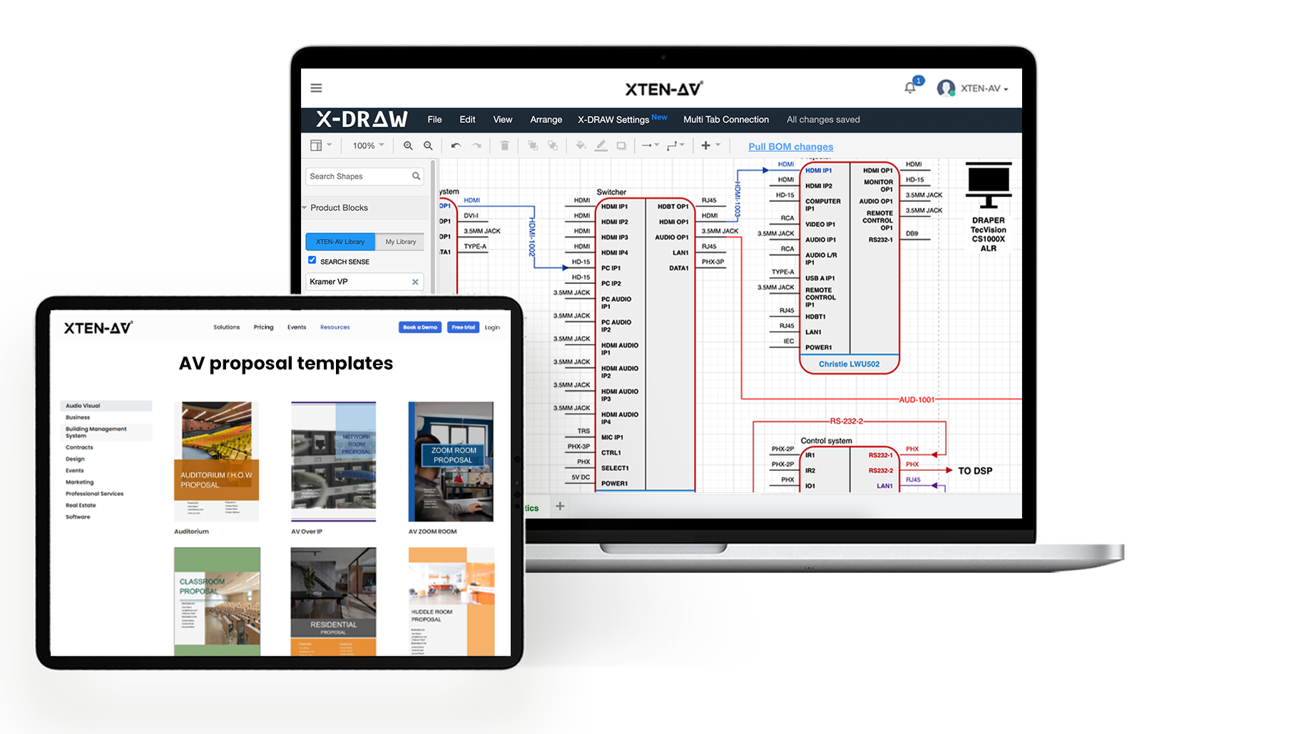
Some teams design in CAD. Equipment list in a spreadsheet. Proposal built by hand. Every revision touches three tools. It takes three times as long. A workflow where docs come from the design saves that time on every project.
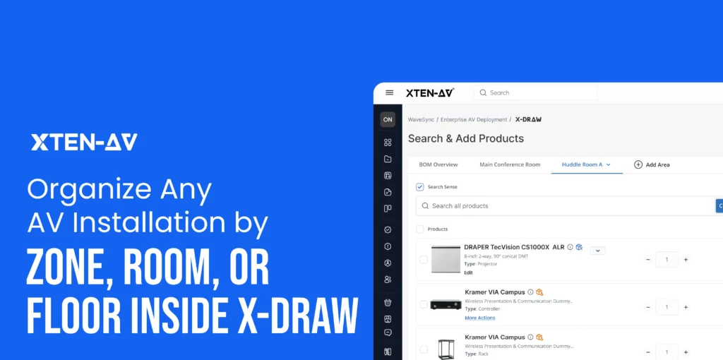
How XTEN-AV Helps Plan and Document Ceiling Speaker Layouts?
The technical challenge is only half the problem. Commercial AV teams also have to keep drawings, BOMs, proposals, and revisions synchronized throughout the project lifecycle
Most ceiling speaker layout work in commercial AV happens across disconnected tools. Coverage radius gets calculated in a spreadsheet. The floor plan lives in CAD. The equipment list is in a quote tool. The proposal is assembled by hand. When the client changes the room boundary two weeks in, the chain breaks and someone spends a morning reassembling it.
XTEN-AV fixes that. It is a commercial AV workflow and documentation platform. Layout, coverage, and docs, all connected. All in sync across every revision.
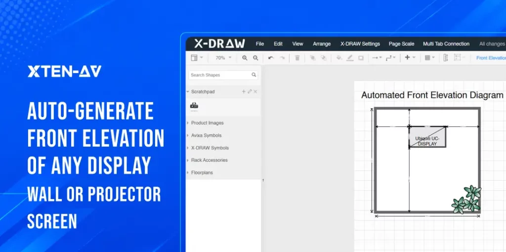
From room input to layout
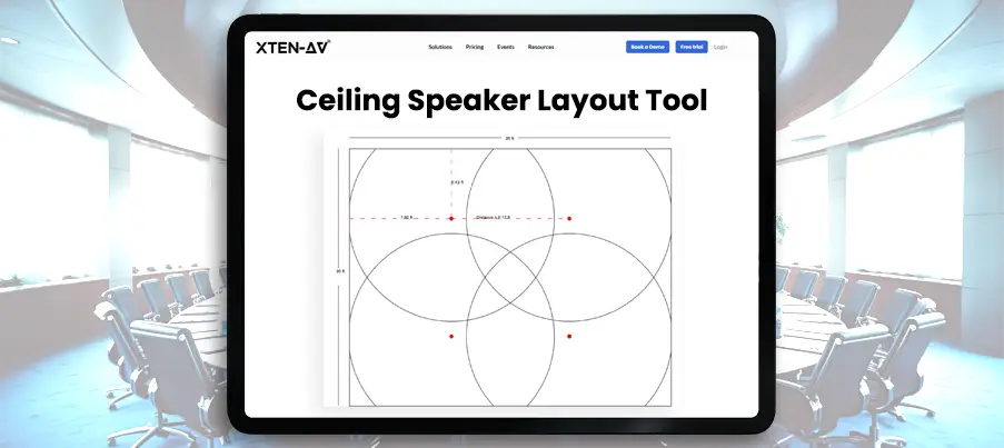
Enter room size and ceiling height. Place speakers on the plan. The ceiling speaker layout calculator computes coverage from dispersion angle and mounting height. It shows zones and gaps before anything is installed.
Seeing gaps at the design stage costs nothing. Finding them during commissioning costs hours.
Documentation that stays attached to the design
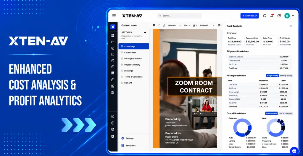
A spreadsheet gives you a speaker count. That is all. It does not give you a layout drawing. It does not give you a proposal or a handover package.
XTEN-AV generates layout diagrams, bills of materials, proposal-ready PDFs, and install docs. When the client changes the layout, the docs update too. No redrawing. No rebuilt quotes.
Repeatability across project types
Most AV teams work the same room types again and again. Office floors. Restaurant builds. Retail rollouts. XTEN-AV lets you adapt a proven layout instead of starting from scratch. Proposals go out faster. Revisions take less time. Every project gets the same standard of docs.
The all-in-one solution for your AV needs
Transform your audio-visual experience with XTEN-AV.
No Credit Card required
Audio Visual System Design Mastery + Winning Proposals = 10x Productivity!
- ✔ Automatic Cable Labeling & Styling
- ✔100+ Free Proposal Templates
- ✔ Upload & Create Floor Plans
- ✔1.5M Products from 5200 Brands
- ✔ AI-powered ‘Search Sense'
- ✔Legally Binding Digital Signatures
Conclusion
Field problems in ceiling speaker installs are almost always design problems.
Wrong speakers count. Missed corners. Ignored ceiling height. 70V and low-Z on the same circuit. Every one of those is visible on paper. Before the first hole is cut.
Most AV teams don’t lose time placing speakers. They lose time revising drawings, rebuilding proposals, and updating documentation after client changes.
XTEN-AV puts it all in one place. Ceiling speaker planning, proposals, and project docs, connected. When the room changes, the chain holds.
Start with the ceiling speaker layout calculator and the ceiling speaker placement guide.
FAQ's
Depends on ceiling height as much as floor area. Calculate the coverage radius at the listening plane using the speaker’s dispersion angle and mounting height, then divide the room into zones from there. The floor area alone gives you the wrong number. Add speakers for corners, they fall outside most grid patterns.
1x to 1.2x the ceiling height is a reasonable starting point; 10 feet of ceiling, 10-12 feet between speakers. Tighten that for boardrooms and classrooms. Background music spaces have more tolerance. The number that actually matters is overlap: 3–6 dB at the midpoint between speakers. Less than that and the gap shows.
Well suited to both, provided spacing and SPL are planned to the right standard. For speech, that means STI above 0.6, which requires tighter spacing and higher speaker density than a music layout. For paging, the layout has to reach every corner of the room, not just the middle.
Cable runs beyond 50–100 feet, more than 8 speakers on an amplifier channel, or anywhere you need per-speaker volume control without adding attenuators. In large public-address environment spaces; warehouses, campuses, multi-floor buildings, 70V isn’t a premium choice. It’s just the right architecture for the scale.
Higher mounting height increases the coverage footprint but drops SPL at the listening plane. You can space speakers wider, but each one has to work harder to hit the target level. Calculate both coverage radius and SPL at the listening plane. Doing only one of them is where field problems start.
Explore more by topic

AV Design Mastery + Winning Proposals = 10x Productivity!
- Automatic Cable Labeling & Styling
- 100+ Free Proposal Templates
- Upload & Create Floor Plans
- 1.5M Products from 5200 Brands
- AI-powered ‘Search Sense'
- Legally Binding Digital Signatures
No Credit Card Required
Related Blogs
-

- Posted by Sahil Dhingra
Audio Visual Multi Room-Wise AV BOM Management Guide Sahil Dhingra Published 24...
-
- Posted by Sahil Dhingra
Audio Visual What Is Location-Based AV Project Management? A Guide for Multi-Room...
-
- Posted by Sahil Dhingra
Audio Visual How to Create AV Front Elevation Drawings for Display Walls...