


How to Create AV Front Elevation Drawings for Display Walls

Sahil Dhingra
Published 18 June 2026
Most AV designers follow the same pattern. They complete the schematic. They finish the floor plan. Then they open CAD or Visio and redraw the same display wall all over again, in a completely separate file.
That third step causes problems. Change a display size or shift the room layout, and you’re updating the schematic, then the elevation, then checking if both files still match. On more than a few projects, those two files disagreed on screen dimensions right up to the installation date.
Display walls, video walls, projector-screen rooms, and camera-equipped conference spaces make this worse. Each one needs a clear front-facing view. Something that shows the wall the way an installer reads it or a client pictures it. A floor plan won’t do that. A signal-flow schematic won’t either.
On many AV projects, the display wall elevation drawing ends up being the most-reviewed drawing in the entire package. Architects use it to verify wall conditions. Facilities teams use it to review mounting locations. Clients use it to approve the visual layout. Installers use it to understand exactly where equipment should sit on the wall. That makes the elevation more than a drawing. It becomes a communication tool across the project lifecycle.
This guide covers how to create AV front elevation drawings correctly. It covers the manual workflow and shows how X-DRAW can generate an editable elevation directly from the AV design. No rebuilding the same wall in a separate tool.
An AV front elevation drawing is a scaled, straight-on view of a wall. It shows where displays, projection screens, cameras, and other wall-mounted AV devices are. They are arranged in vertical and horizontal orientations. |
Key Takeaways
- The front elevation displays the AV wall layout from a straight-on view. It’s not seen from above or as a wiring diagram.
- Display-wall elevations should include wall dimensions, display size, arrangement, mounting relationships, and camera placement where relevant.
- Front elevations complement floor plans and schematics. They don’t replace them.
- Manual redrawing increases revision effort every time a display-wall layout changes.
- X-DRAW can generate an editable front elevation for displays and projector screens inside the same AV design workflow.
The all-in-one solution for your Audio Visual (AV) Project Design & Documentation needs
Transform your audio-visual experience with XTEN-AV.
No Credit Card required
What Is an AV Front Elevation Drawing?
An AV front elevation drawing is a scaled, straight-on representation of a wall. It shows where displays, projection screens, cameras, control switches, and other wall-mounted AV components sit vertically and horizontally, relative to the wall and each other.
Think of it this way. A floor plan shows the room from above. A schematic shows how signals travel through the system. An elevation shows the front wall as a person standing in the room would actually see it.
That perspective matters more than most designers give it credit for. Clients struggle to visualize display placement from a top-down room drawing. Installers care less about signal flow and more about what height the display mounts at and how far it sits from the adjacent markerboard. An elevation answers both of those questions at a glance.
How is an AV elevation different from an architectural elevation?
Architectural elevations cover facades, windows, doors, and materials. AV front elevations focus on equipment. Where the display sits. How high the camera mounts. How devices relate to each other on the same wall. The wall is just the backdrop. The AV gear is what the drawing is actually about.
A drawing without scale is a sketch. Scale lets a reviewer check whether a 98-inch display fits between two columns at the right mounting height. It lets a client confirm the active image area works for seated viewers in that room. AVIXA’s display image size guidance ties display selection directly to content type, viewing distance, and image area. None of that holds up on a drawing that isn’t to scale.
How Is a Front Elevation Different From Other AV Drawings?
Each drawing type in an AV documentation package serves a different purpose. Mixing them up, or relying on one to do the job of another is a common source of coordination problems.
Drawing Type | Perspective | Main Purpose | Typical AV Details |
Front Elevation | Straight-on wall view | Document vertical wall layout | Displays, screens, cameras, mounting relationships |
Floor Plan | Top-down room view | Document room layout and placement | Equipment location, seating, cable pathways |
AV Schematic | Functional connection view | Show signal routing | Sources, switchers, DSPs, displays, cables |
Rack Elevation | Front or rear rack view | Plan equipment-rack layout | Rack units, device order, ventilation, access |
Reflected Ceiling Plan | Ceiling-facing plan view | Document overhead devices | Speakers, microphones, projectors, sensors |
Notice that each drawing answers a different question. The front elevation answers: what does the wall look like? The rack elevation diagram answers: how is the rack loaded?
Mixing them up happens more than it should. Usually on teams where one person is doing both the design and the documentation and moving fast.
For AV schematic documentation, the guide to AV schematic diagrams covers signal-flow drawing best practices.
Why Do Display-Wall Projects Need Front Elevation Drawings?
A display wall isn’t just a product pick. It’s a spatial decision. How many screens. How high they mount. How they align. Whether the bezel gaps matter. Where the camera sits. A schematic doesn’t answer any of that. A floor plan might show a display exists in the room. It won’t tell you if the screen centerline is at 1,400 mm AFF or 1,650 mm AFF.
Client review
Most clients don’t read schematics. Show someone a signal-flow diagram and they’ll nod. They won’t actually know what the finished wall looks like.
An elevation fixes that. Clients can see the wall. They can see where each display sits. They can spot problems before the hardware ships, not after brackets are drilled into drywall.
Installation coordination
Installers need:
- Mounting heights
- Display centerlines
- AFF measurements
- Horizontal offsets
- The spatial relationship between displays and cameras.
They need the front-facing view.
AV design standards from institutions like Central Washington University explicitly include scaled wall elevations. Alongside floor plans, schematics, and equipment schedules.
Revision control
Display size changes from 86 inches to 98 inches. The elevation needs to be updated. If it lives in a separate file, that update is a manual step. Easy to skip. Easy to forget.
Mismatched documentation can create additional clarification requests during installation. That call costs time. And the fix usually costs more.
Camera context in meeting rooms
Conference rooms and boardrooms almost always involve a camera now. That camera needs to sit in a specific position relative to the display, above it, below it, or between two screens.
A schematic won’t show that. An elevation will. Clients can approve the layout before anything gets mounted.
AV submittal packages
AVIXA’s documentation needs for audiovisual systems include scaled drawings as a key element. A full submittal package consists of floor plans, schematics, equipment schedules, rack layouts, and wall elevations.
Leave out the elevation and that gap shows up during coordination review. It’s one of those things that’s easy to overlook and annoying to fix late.
What Should an AV Display-Wall Front Elevation Include?
A useful display wall elevation diagram contains more than just the display outline. Every element listed below affects how the drawing is used, by reviewers, coordinators, and field teams.
Drawing Element | Why It Matters | Questions to Confirm |
Wall width and height | Establishes the usable drawing area | Is the mounting wall measured accurately? |
Display quantity | Defines the layout | One display, dual displays, or multi-display wall? |
Physical display dimensions | Shows equipment footprint | Do the selected products fit the available wall space? |
Active image area | Supports viewing-position planning | Is the visible content area suitable for room depth? |
Mounting height | Clarifies vertical placement | Is the display centerline or lower edge positioned correctly? |
Horizontal alignment | Keeps the wall visually balanced | Are displays centered or intentionally offset? |
Inter-display spacing | Affects multi-display layouts | Does the gap or bezel relationship need to be shown? |
Camera position | Clarifies conferencing layout | Is the camera above, below, or between the displays? |
Wall-mounted controls | Supports installation coordination | Are control switches or touch-panel docks relevant? |
Architectural obstructions | Prevents placement conflicts | Are doors, windows, columns, or markerboards present? |
Notes and dimensions | Helps reviewers interpret the view | Are mounting offsets and AFF measurements labelled? |
Scale and title block | Supports professional documentation | Can the drawing be reviewed and versioned clearly? |
Physical dimensions vs. active image area.
This is one of the most frequently misunderstood distinctions in display-wall documentation.
Physical display dimensions cover the full outer footprint, bezel, frame, everything. The active image area is just the part where content actually shows up. That gap between the two numbers matters more than most drawings reflect.
Here’s a real scenario. A conference room is designed for spreadsheet review. The display fits the wall. But the active image area is too small for anyone seated past the third row. The wall space worked. The screen didn’t.
AVIXA guidance recommends selecting display size based on viewing distance and content requirements, not simply wall availability. That is why elevations should document both the display footprint and the visible image area when those measurements affect design decisions.
Leave one out and a client approves the layout based on the wrong dimension. The installed system looks different from the drawing. That conversation is never a good one.
What Should You Confirm Before Drawing a Display-Wall Elevation?
Starting the drawing before you have the right inputs wastes everyone’s time. Run through these first.
What is the room used for?
A boardroom with dual 86-inch displays and a camera is a different drawing than a lobby signage wall with four 55-inch panels. The use case shapes everything.
How large is the available wall surface?
Get the exact width and height. Check for columns, windows, conduit chases, and markerboard positions. These constrain where equipment can actually go.
Flat panels, video wall, or projection screen?
The drawing approach changes depending on the answer. So do the required dimensions.
How many displays are in this elevation?
For multi-display walls, confirm the arrangement, alignment, and whether bezel gaps need to show up in the drawing.
Where does the camera sit?
For conference rooms, nail down whether the camera goes above, below, or between the displays and whether it belongs in this elevation at all.
What does the client need to approve?
Some clients just want to confirm how the wall looks. Others need to verify mounting heights against facility standards. Know which before you draw.
What does the installation team need?
Field teams want AFF dimensions, horizontal offsets, display model references, and notes on mounting constraints. Give them what they’ll actually use on site.
A screen size calculator can help validate display sizing before you lock in dimensions. For projector-screen setups, a projector throw-distance calculator can help validate throw distance and image size before drawing.
The video wall vs projector guide covers the configuration decisions that affect what the elevation needs to document.
How Do You Create an AV Front Elevation Drawing Manually?
Manual drafting still works. It’s the right call for custom configurations or when a designer wants full control over every dimension and annotation. Here’s the process.
Step 1: Measure the front wall
Collect the wall width, height, and usable mounting surface. Note every constraint: columns, windows, doorframes, markerboards, conduit runs, existing fixtures. Anything that limits where equipment can go.
Step 2: Confirm the display configuration
One flat panel. Dual displays. Up to four screens in a row. A video wall. A projection-screen setup. Pin this down before anything else. The configuration drives every other decision in the drawing.
Step 3: Add display dimensions
Draw the physical footprint. Then mark the active image area separately. Don’t treat them as the same number, they’re not. If both appear in the elevation, label them clearly so no reviewer guesses which is which.
Step 4: Position the displays
Set the horizontal alignment, vertical height, screen centerline, bottom-edge AFF, inter-display gaps, and wall offsets. The most common mistake is eyeballing the position instead of using verified wall measurements. Don’t make that mistake.
Step 5: Add the camera and related devices
For conference rooms and boardrooms, show the camera and its position relative to the displays. Add control switches, touch panels, or other wall-mounted devices where they affect installation or coordination.
Step 6: Add dimensions and notes
Label offsets, mounting heights, AFF references, scale, drawing title, and revision details. An elevation without dimension annotations is fine for an aesthetics review. It’s not enough for an installation handoff.
Step 7: Check the elevation against the rest of the design
Compare it against the BOM, floor plan, schematic, client requirements, and submittal package. If a display size changed after the last schematic revision, the elevation may already be wrong.
Manual drafting is solid for one-off projects. It gets painful when display sizes change, layouts shift, or value engineering kicks in late. Every revision means parallel updates across disconnected files. For more on where AV CAD drawing challenges create friction, see the guide covering the most common workflow pain points.
EXAMPLE 1: Dual-Display Boardroom Wall: 5,400 mm wide. 3,000 mm high. Configuration: Two 86-inch commercial displays. Mounted side by side. 150 mm gap between them. Display centerline at 1,500 mm AFF. Camera: PTZ camera sits centrally between the two screens, roughly 300 mm below their top edge. Wall offsets: 450 mm from the left wall. 430 mm from the right. Bottom edge of displays at 1,150 mm AFF. Without a front elevation, this boardroom’s camera-to-display relationship is invisible in the schematic. The floor plan shows only that equipment exists, not how it sits on the wall. A client reviewing this room remotely needs the elevation to confirm the layout before approving the design. |
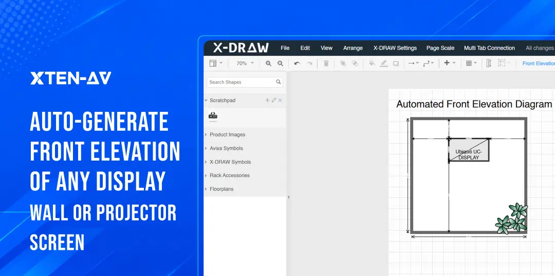
How Can X-DRAW Generate an AV Front Elevation Diagram?
Most AV teams already know how to draw an elevation. The challenge is maintaining that elevation after the design changes. A display-size revision, camera relocation, or layout adjustment often means reopening a separate drafting tool and rebuilding the wall view manually.
AV design and drawing software X-DRAW helps AV designers generate an editable, scale-accurate front elevation by using project-specific wall and screen inputs inside the existing AV design workflow. The goal is to reduce the need to recreate the same wall layout manually in a separate drafting tool after the design is already complete.
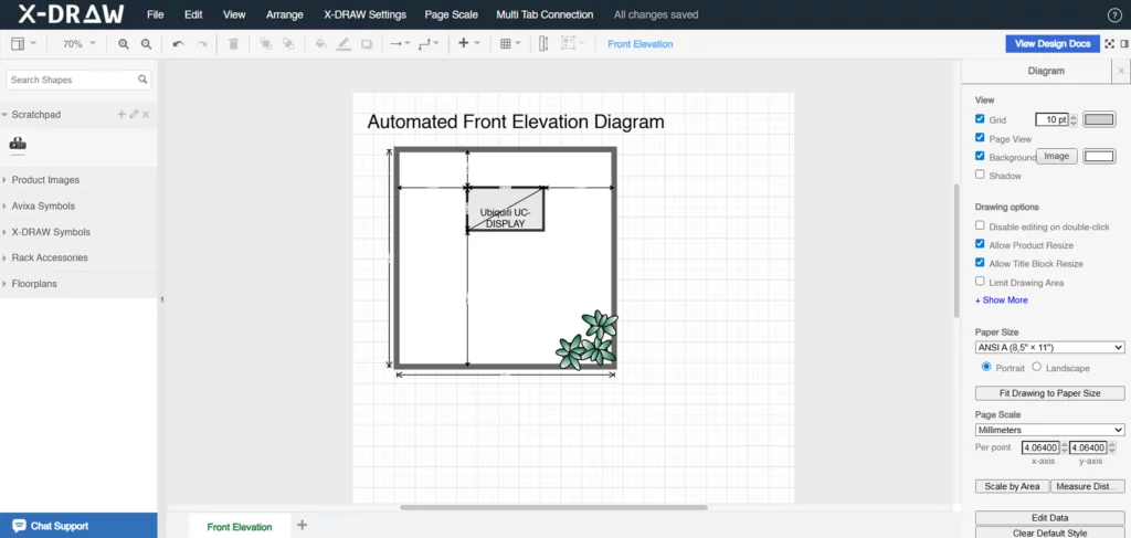
Steps to generate an AV Front Elevation Diagram using AV Drawing Software X-DRAW:
- Open the design.
Navigate to the design for which the front elevation is required inside X-DRAW.
- Open Automated Front Elevation Diagram.
Use the Front Elevation Diagram workflow inside the design-documentation area.
- Add the wall width, wall height, and unit of measurement.
- Select the screen type.
Choose Display or Projector Screen, depending on the project configuration.
- Select products and quantity.
Choose the display products and the quantity required for the wall elevation.
- Add a camera where required.
Select the relevant camera for the elevation. Cameras are added one at a time.
- Verify screen dimensions.
Review and update the selected screen dimensions before saving.
- Open the generated elevation in the editor.
The drawing opens inside X-DRAW for further editing.
- Add or adjust dimension annotations.
Dimension annotations are added or adjusted inside the X-DRAW editor after the elevation is generated. They are not placed automatically.
Current X-DRAW front-elevation support:
|
Stop drawing the same display wall twice. Generate editable AV front elevation diagrams inside X-DRAW and keep your design documentation in one connected workflow. |
How Should You Review a Display-Wall Elevation Before Sharing It?
A drawing shared prematurely wastes everyone’s time. Run through this checklist before the elevation goes to a client or installation team.
- Confirm wall width and height match the verified site measurements.
- Verify each display model and its physical dimensions against the current BOM.
- Confirm display quantity is correct.
- Check horizontal and vertical alignment are displays centered, or is an intentional offset documented?
- Review the display centerline or bottom-edge AFF mounting relationship.
- Verify inter-display spacing where relevant to the layout.
- Confirm camera placement: position, orientation, and relationship to the displays.
- Check for architectural obstructions: doors, windows, markerboards, alcoves, columns, or nearby devices.
- Add critical dimensions and AFF notes where the installation team needs them.
- Confirm the title block and revision information are up to date.
- Compare the elevation with the current BOM.
- Compare the elevation with the AV schematic.
- Compare the elevation with the floor plan.
- Confirm the drawing is suitable for the intended use: client review, coordination, or installation handoff.
How Do Front Elevation Drawings Support AV Submittals and Installation?
A wall elevation is one of the clearest communication tools in an AV project package. It bridges the gap between system design and physical installation.
Submittal review
During design review, an elevation gives clients, architects, and facilities managers a drawing they can read without AV training. They can check that display positions match the room design, that the camera sits at an acceptable location, and that the wall layout aligns with their expectations. Issues caught at this stage cost far less than corrections made after mounting brackets are installed.
Fewer clarification calls
Every RFI that comes back from a site visit because a dimension wasn’t documented costs time and can delay a project. A complete elevation, with AFF heights, offsets, display models, and camera positions clearly noted, reduces those requests.
Revision consistency
When a client requests a display-size change during value engineering, the elevation must update alongside the BOM and schematic. Teams that keep the elevation inside the same AV workflow as the rest of the design are better positioned to catch and resolve these discrepancies before they reach the installation phase.
EXAMPLE 2: Training Room With Projection Screen Wall: 7,200 mm wide x 3,000 mm high. Configuration: One 3,000 mm wide projection screen at 2,200 mm image height. Screen bottom edge at 900 mm AFF. Markerboard to the left of the screen, 1,800 mm wide x 1,200 mm high. Camera positioned above the screen, centrally aligned. Wall controls: Touch panel dock at 1,100 mm AFF, 400 mm right of the right wall edge. In this training room, the elevation confirms the spatial relationship between the projection screen, the markerboard, and the camera, none of which are visible on a floor plan. It also shows that the touch panel position clears the screen by a safe margin. |
Where Are AV Front Elevation Drawings Most Useful?
Wall elevations matter most where wall-mounted visual systems and cameras need to be reviewed before installation. These are the environments where front elevations carry the most documentation weight.
Use Case | Why the Elevation Matters | Key Elements |
Boardroom | Supports display and camera review | Dual displays, camera, wall dimensions, AFF heights |
Conference Room | Clarifies conferencing layout | Display height, camera position, wall controls |
Training Room | Supports visibility and instructor-facing layout | Displays, projection screen, camera, markerboard |
Classroom | Documents projection-screen and teaching-wall setup | Screen, active image area, markerboard, controls |
Auditorium | Clarifies large-screen placement | Projection screen, image size, wall height |
Digital Signage | Visualises multi-display arrangement | Display quantity, alignment, spacing |
Command Center | Supports multi-screen planning | Multiple displays, arrangement, sightlines |
Control Room | Documents operator-facing visual layout | Display wall, spacing, mounting relationships |
EXAMPLE 3: Digital-Signage Display Wall Wall: 6,400 mm wide x 2,800 mm high. Configuration: Four 55-inch commercial displays in a horizontal row. 10 mm inter-display gap. Bottom edge of all displays at 600 mm AFF for low-height retail visibility. Alignment: Display centerlines aligned horizontally at 960 mm AFF. This layout looks straightforward on paper. But when a client requests a layout change, say, replacing four 55-inch panels with three 75-inch displays, the entire elevation needs to be redrawn. Wall offsets change, center positions shift, and the AFF relationships update. In a disconnected drafting workflow, that’s a manual rebuild. In X-DRAW, it means re-selecting the products and regenerating the elevation. |
How Does Front-Elevation Automation Improve AV Documentation Workflows?
Manual drafting splits the project in two. The AV design lives in one place. The elevation lives somewhere else. That gap starts small. By the third revision, it’s a real problem.
Duplicate work
The moment a designer redraws the display wall in a separate tool, the two files start drifting apart. One gets updated. The other doesn’t. That mismatch is quiet until someone catches it on site.
Revision management
Display size changes. Layout shifts. The camera moves. Value engineering comes in late. Every one of those changes needs a parallel update in the elevation file. Miss one and the documentation is wrong. Keeping elevation generation inside the same workflow as the design removes that extra step.
Installation coordination
Field teams work better with a complete package. Schematic. Floor plan. Current elevation. All three together. The elevation doesn’t replace the schematic, it finishes the set. Fewer questions come back from site when the wall drawing is actually there.
Documentation consistency
An editable elevation output gives designers a base to work from, not a finished product to accept as-is. They open it, add annotations, refine what needs refining, and export a clean drawing. The automation handles the spatial rebuild. The designer handles the judgment calls.
That’s the split worth understanding. Automation doesn’t remove the designer from the process. It removes the part where they redraw the same wall outline for the fourth time.
What Is the Best Way to Create AV Front Elevations for Display Walls?
Manual elevation drawings are still a valid option. For custom setups, unusual wall shapes, or when a designer wants total control over dimensions, manual drafting works best.
The problem isn’t the first drawing. It’s the fifth.
Three rounds of display-size changes. A value-engineering swap. A late camera reposition. That’s five or six full redraws of the same wall in a disconnected tool. Each one is engineering time spent rebuilding a layout instead of making design decisions.
X-DRAW cuts that loop. Teams create a front elevation that can be edited. This helps with displays and projector-screen setups, all within the AV design workflow. The output opens in the editor. Designers add annotations, refine details, and share it. When something changes, they update, not rebuild.
The best approach is the one that gets to an accurate, shareable elevation with the least repeated work. For most display-wall projects, that’s keeping elevation generation inside the same workflow as everything else.
Generate AV front elevations faster with X-DRAW AV designers shouldn’t have to redraw the same display wall after every revision. X-DRAW creates editable, scale-accurate front elevation diagrams for display walls and projector screens. You can open the elevation, add annotations, and share it. There’s no need to rebuild the layout in another tool. Explore AV design and drawing software X-DRAW. |
The all-in-one solution for your AV needs
Transform your audio-visual experience with XTEN-AV.
No Credit Card required
Audio Visual System Design Mastery + Winning Proposals = 10x Productivity!
- ✔ Automatic Cable Labeling & Styling
- ✔100+ Free Proposal Templates
- ✔ Upload & Create Floor Plans
- ✔1.5M Products from 5200 Brands
- ✔ AI-powered ‘Search Sense'
- ✔Legally Binding Digital Signatures
FAQ's
It’s a scaled, straight-on view of a wall. It shows where displays, projection screens, cameras, and wall-mounted AV devices will sit. A floor plan shows the room from above. A schematic shows signal flow. An elevation shows the wall the way a person standing in the room actually sees it, mounting heights, positions, and all.
Wall dimensions. Display quantity. Physical screen dimensions. Active image area. Mounting height above finished floor (AFF). Horizontal alignment. Inter-display spacing where it matters. Camera position. Architectural obstructions. Dimension annotations. A drawing scale and title block. Leave any of these out and someone downstream will ask for them.
A floor plan shows the room from above. An elevation shows the wall straight on. Both belong in a complete AV documentation package. Neither one does the other’s job.
No. A front elevation shows what’s on the room wall, displays, screens, cameras, controls. A rack elevation shows what’s inside the equipment rack. Different drawings. Different purposes. Different teams use it on site.
Because unscaled drawings cause problems.
Scaled elevations help teams:
- Check equipment placement before installation.
- Coordinate mounting heights with installers.
- Provide clients with accurate details for approval.
Missing or unscaled elevations are behind more field clarification calls than most people track.
X-DRAW generates an editable front elevation using wall dimensions and screen inputs from the AV design workflow. The output opens in the X-DRAW editor. Designers add or adjust dimension annotations there before sharing or exporting.
Up to four. That covers single displays, dual-display layouts, and multi-screen walls up to four panels.
Yes. Up to two projection screens per elevation. That covers single-screen and dual-screen setups in training rooms, auditoriums, and classrooms.
Yes. Select the camera and it gets added to the diagram. One camera at a time in the current workflow. Useful for any room where the camera-to-display relationship needs to be documented clearly.
No. The elevation generated from the wall and screen inputs you enter. After that, designers add or adjust dimension annotations inside the X-DRAW editor. That part stays in the designer’s hands.
Explore more by topic

AV Design Mastery + Winning Proposals = 10x Productivity!
- Automatic Cable Labeling & Styling
- 100+ Free Proposal Templates
- Upload & Create Floor Plans
- 1.5M Products from 5200 Brands
- AI-powered ‘Search Sense'
- Legally Binding Digital Signatures
No Credit Card Required
Related Blogs

-

- Posted by Sahil Dhingra
Audio Visual A Complete Guide to Commercial AV Companies: What to Expect,...

-
- Posted by Sahil Dhingra
Audio Visual 6 Best Field Service Management Software for Audio Visual (AV)...
-
- Posted by Sahil Dhingra
Audio Visual What Is an AV Connection Check and Why Does It...